89 951 engine overhaul

Talk and Tech about turbocharged 924/944/968 cars
User avatar
Dare
Posts: 32
Joined: Wed Mar 16, 2022 3:03 pm
Location: San Jose / Palm Springs
Has thanked: 19 times
Been thanked: 16 times
four0four wrote: Tue Apr 12, 2022 6:33 pm If I go any more DIY I'd be laying out a board instead of working on the car...Speeduino is a great idea, but the code leaves a little to be desired.
Somewhat of a tangent, but I'd be interested to hear your thoughts on the Speeduino code. After I finish my Microsquirt adaptation (some details here) I was thinking of redesigned my board to use Speeduino.
Oh, my bore gauges are the kind you need to measure after locking in. Not the kind with a built-in dial indicator.
You must have a better sense of feel than I do. I had quite a bit of difficulty getting reliable readings using a telescoping bore gauge. Ending up buying used Starrett 84.
Jay
2012 Porsche Cayman R
1986 Porsche 944 Turbo

Jay's Porsche Project

#31

User avatar
four0four
Posts: 184
Joined: Wed Feb 02, 2022 10:09 pm
Location: Western WA
Has thanked: 22 times
Been thanked: 32 times
Dare wrote: Sat Apr 16, 2022 1:36 pm
four0four wrote: Tue Apr 12, 2022 6:33 pm If I go any more DIY I'd be laying out a board instead of working on the car...Speeduino is a great idea, but the code leaves a little to be desired.
Somewhat of a tangent, but I'd be interested to hear your thoughts on the Speeduino code. After I finish my Microsquirt adaptation (some details here) I was thinking of redesigned my board to use Speeduino.
Hah, I've seen your thread/blog :)

For sure it's capable of driving a 944! I think I was just curious about how some problems were approached by ECUs (and I hate hate hate reading 8051 assembly, so I looked at Speeduino). I believe I was looking at boost control stuff, I half finished a standalone boost controller (lazy-electronics style: so perf boards, a couple jellybean FETs, and an Teensy LC. this was at peak chip shortage, and I didn't want to even look at Digikey).

I'd have to go hunting again, but the code is very "MechE" (no disrespect!), if that makes sense. There are also a fair few weird design decisions that stem from how, I think, TunerStudio expects ECUs to work.

Now, I think an FPGA-based ECU would be, if not particularly better, very novel.
Oh, my bore gauges are the kind you need to measure after locking in. Not the kind with a built-in dial indicator.
You must have a better sense of feel than I do. I had quite a bit of difficulty getting reliable readings using a telescoping bore gauge. Ending up buying used Starrett 84.
There's a bit of a trick to it. I'm shocked they're (considered?) as precise as they are, but basically you're trying to sweep it along a region where your measurement is the low inflection point of the path traced by the moving tip (the other should be mostly fixed). Once I figured out how it worked it kinda clicked.

#32

User avatar
four0four
Posts: 184
Joined: Wed Feb 02, 2022 10:09 pm
Location: Western WA
Has thanked: 22 times
Been thanked: 32 times
OK, bore gauges are kind of a pain in the ass once you've done the same measurement half a dozen times...


Anyway, bores seem to continue to be good? I'm not confident in my 0.1 thou digit (and group 0 to group 2 deviation is about 0.8 thou...). Per the WSM measurement procedure I'm between 0 and 1 (this tracks: group 0 rods. haven't cleared off the pistons yet). Taper and out-of-round isn't more than a thou off the rest of the bore as far as I could tell.


I have no real idea how acceptable this is! Beyond my bias against sending the block out that is :D

Is there something I'm missing wrt popping the pistons out the top? I messed with it a bit before leaving, but didn't get anywhere. It feels wrong to smack one of the rod bolts at a time...

I'll re-evaluate this once I get the pistons out and the bottom of the bores measured.

#33

User avatar
Tom
Site Admin
Posts: 8923
Joined: Fri Jun 25, 2021 2:04 pm
Location: Silicon Valley, CA
Has thanked: 932 times
Been thanked: 3991 times
Contact:
On traditional motors, you'd need to worry about cylinder ridge at the top of the cylinders. That's the short little area between the top of the cylinder and the highest point the top ring reaches. Because the rings are constantly wearing away at the cylinders and keeping them clean, a little ridge can develop between the ring-swept part of the cylinder and the upper little bit above that. On these motors, it tends to be less of an issue from what I've seen, but you still can get a ridge of carbon and sludge. On 'regular' motors, people use a ridge reamer to remove the ridge so the pistons pop out without catching on anything. I honestly don't know if there is any way to do the same on an alusil motor, other than chemically removing any carbon/varnish. I think most people just pull out the pistons and go from there based on how smoothly (or not) they come out.

#34

User avatar
four0four
Posts: 184
Joined: Wed Feb 02, 2022 10:09 pm
Location: Western WA
Has thanked: 22 times
Been thanked: 32 times
Turns out piston rings are sharp! Between that and the wrist pins I did a number on my hands...oh well, blood sweat and all that ;)
pistons.jpg
pistons.jpg (3.13 MiB) Viewed 1506 times
I left my measurements at the garage (real smart, me) - and I've yet to sit down and do the math on clearances (which I recognize is the real figure of merit here)...but the pistons had sizes erring on the low side of tolerance at the high points, and out of tolerance at the low points (lowest near the first ring, then the burnished side skirt).

How much of an issue is this? I'm not opposed to finding new pistons, but I also don't have a feel for how bad wear here is.


Also, pretty sure I caught something when removing this guy :(
oops.jpg
oops.jpg (2.11 MiB) Viewed 1506 times

edit: Thanks, Tom - I just hit the ridge with some acetone and elbow grease. The varnish on the lower third of the bores will take a little more of the each...

edit, redux: Pistons are tolerance group 1. This is odd, 'cause I thought the rods were 0 (based on a stamp on the bottom of the big end), but I guess I'm incorrect there.

#35

User avatar
chris white
Posts: 434
Joined: Wed Aug 11, 2021 11:40 am
Been thanked: 175 times
Ok, first thing is that the rods do not have any tolerance markings on them. Not sure what you are seeing there. 2nd - pistons are measured about 1” from the bottom of the skirt, pistons are not ‘straight’ , they have a vertical curve to the skirts.
The main thing you are looking for is a taper to the bore, that’s the thing that wears rinds out

#36

User avatar
four0four
Posts: 184
Joined: Wed Feb 02, 2022 10:09 pm
Location: Western WA
Has thanked: 22 times
Been thanked: 32 times
There's a stamp on the rod caps - Obviously for some other purpose :)

Aha! Ok, there was something I didn't know I didn't know, thanks chris!

I'm assuming then the taper should be measured along the portion of the cylinder the rings land - Will shoot for top/middle/bottom at 90 deg and 0 deg.

#37

User avatar
four0four
Posts: 184
Joined: Wed Feb 02, 2022 10:09 pm
Location: Western WA
Has thanked: 22 times
Been thanked: 32 times
OK, grabbed my measurements. Everything in thousandths/inches 'cause that's what my mics are.

Pistons: #1: 3.9357 #2: 3.9356 #3: 3.9356 #4: 3.9357

Measured per the workshop manual location.


For measuring the bores, I took 5: The top, the "middle", the bottom (along the ring's travel) and the bottom *after* the rings. Finally, 62mm per WSM.

Bores (Top/Middle/Bottom/Bottom-er):

#1: 3.9385/3.9380/3.9380/3.9375
#2: 3.9384/3.9383/3.9376/3.9375
#3: 3.9385/3.9376/3.9380/3.9373 (I re-took this a lot, was a little surprising. perhaps my instruments run short)
#4: 3.9381/3.9376/3.9376/3.9375

3.9375 makes sense for a mostly unworn bore, it's right just over the midpoint of group 1's tolerance band.

And per WSM @ 62mm depth (whoops, should be 65mm. I wasn't within 3mm anyway):
#1: 3.9376 (hmm...)
#2: 3.9378
#3: 3.9378
#4: 3.9378

This leaves my clearances ranging from 2.85ish to 2.0, with the 62mm point sitting constantly at 2.1 and 2.2. WSM specifies factory tolerance 0.315 -> 1.25 thou with 3.15 thou wear limit. Assuming that's along a radius this puts me, shockingly, just within factory numbers. Doubting my measurements a little in light of this!

Anyway, assuming that's correct, I feel OK just re-using pistons. I did gouge one (can pick it up with a nail...seen in a previous post) in the lower skirt removing it. Hopefully I can get the sides taken back to the tighter end of factory tolerance and make up for that by shipping these off to get coated. iirc swaintech maintains they can bring up 4 thou of thickness (radially i assume, again), which is far more than sufficient.


It wasn't all roses, however :( :
dammit.jpg
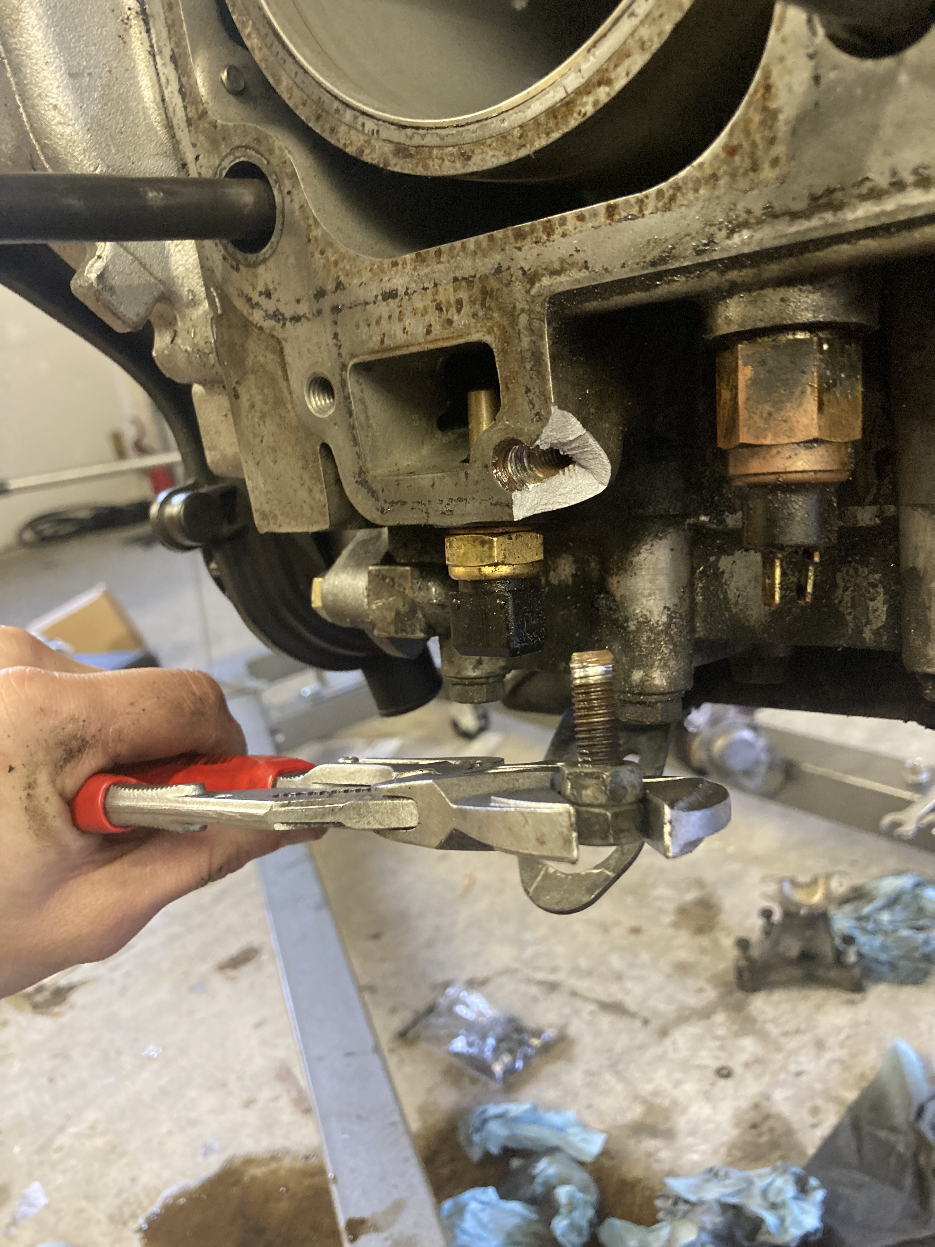
dammit.jpg (2.33 MiB) Viewed 1437 times
...Going to just find some decent epoxy (jb weld? eek.) re-drill and fit a thread insert, then convert those two bolts to studs.

#38

User avatar
Tom
Site Admin
Posts: 8923
Joined: Fri Jun 25, 2021 2:04 pm
Location: Silicon Valley, CA
Has thanked: 932 times
Been thanked: 3991 times
Contact:
Re the broken chunk, I'm not sure I'd bother with JB weld or the like -- just kind of doubt it would do much? If there is enough material below, maybe just tap it as is? That inner area 'should' seal the coolant.

A decent TIG machine would build that back up no problem. The new generation of welders are so small that someone 'could' bring one over to your garage. Decking the top might be a challenge, but for such a small and non-critical area, I'm guessing you could 'deck' it good enough with a dremel or the like.

If not TIG handy, that broken bit is a perfect candidate for HTS-2000 and/or similar brazing rods sold at HF and other places. I've used HTS-2000 and it's the real deal. If you create a little steal or copper fence for it, it would be stronger than new... Here is a cheesy video, but worth watching for your situation....


#39

User avatar
chris white
Posts: 434
Joined: Wed Aug 11, 2021 11:40 am
Been thanked: 175 times
I would tap the hole to clean it up and install a long stud with loctite.

#40

Post Reply