


I was about to start documenting how the fuel maps work when I realized I really needed to explain how the DME engine load is calculated first. This step has for some reason usually been called the "transfer function" by others over the years. It's a bit cryptic in how it works but not hugely complicated. The end result is a number that combines rpm and airflow and serves as the actual fuel injector base pulse width.
The reason for the "cryptic" part of the code is that the AFM's output is logarithmic, not linear, with respect to airflow, and the code linearizes it in a weird unconventional way.
That logarithmic curve very deliberate. I know it's deliberate because the potentiometer part is actually linear, so the logarithmic curve must be coming from the physical shape, which took some trouble to get right (look at the curve of the air channel). The logical reason I would guess is that this gives more of the available resolution (which is very limited) to the low/medium airflow ranges, where better sensitivity and accuracy are needed for driveability.
Anyway here is my attempt at explaining all this in 2 parts - first an overview with lots of pictures and then a code walkthrough with fewer pictures (but still not zero).
https://jhnbyrn.github.io/951-KLR-PAGES ... ation.html
https://jhnbyrn.github.io/951-KLR-PAGES ... rough.html
Maybe I should update it with some physical details of the AFM. I have a spare one that I could probably get some pics of and maybe create a diagram.
Anyway the reason all this is important when it comes to fuel maps is that the maps don't really contain anything that can meter out fuel in proportion to airflow, which obviously is needed. That's done by the base fuel pulse explained here. The maps really just stretch or shrink the base pulse a little bit here or there to target different AFRs. If you're looking in the raw maps, any place you see "128", that means 14.7:1, higher means richer, lower means leaner. But the details of how all that works will have to wait for another documentation drop!
How the DME calculates load, i.e. the Transfer Function
-
ROB III
- Moderator
- Posts: 601
- Joined: Fri Mar 25, 2022 2:47 pm
- Location: Nashville
- Has thanked: 520 times
- Been thanked: 262 times
@johnb
Amazing....thank you for taking the time to put these together and share them.
Can't say I can follow the second attachment but the first REALLY helps explain A LOT.

Amazing....thank you for taking the time to put these together and share them.
Can't say I can follow the second attachment but the first REALLY helps explain A LOT.
Rob
89 944 Turbo
Musik-Stadt Region
89 944 Turbo
Musik-Stadt Region
-
walfreyydo

- Posts: 136
- Joined: Wed Dec 11, 2024 7:28 am
- Location: Wisconsin
- Has thanked: 28 times
- Been thanked: 57 times
- Contact:
Some good info here:
https://tunertools.com/pages/load-contr ... o2dWgV9pXc
If I am not mistaken, most modern EFI systems either use the MAF(AFM), speed density or alpha-n algorithms. The "MAF" load calculation model uses airflow -- in the case of the 944, an AFM-- intake temp, rpm and engine displacement. I would think the 944, using the AFM/MAF algorithm is no different?
Alot of the specifics you posted in those two articles are over my head, but in terms of load calculation the equation is pretty universal, when it comes to MAF systems?
89 S2 Variocam, Megasquirt DIYPNP
Garage
Garage
I couldn't say much about how other cars do it but the 944 doesn't do anything as sophisticated as the formula shown there. It doesn't know MAP and for air temperature, it just multiplies the fuel pulse using this function (map 42):walfreyydo wrote: Tue Nov 25, 2025 6:14 am Some good info here:
https://tunertools.com/pages/load-contr ... o2dWgV9pXc
If I am not mistaken, most modern EFI systems either use the MAF(AFM), speed density or alpha-n algorithms. The "MAF" load calculation model uses airflow -- in the case of the 944, an AFM-- intake temp, rpm and engine displacement. I would think the 944, using the AFM/MAF algorithm is no different?
Alot of the specifics you posted in those two articles are over my head, but in terms of load calculation the equation is pretty universal, when it comes to MAF systems?
- map_42_air_temp_fuel_compensation.png (30.06 KiB) Viewed 949 times
As you can see it does nothing above 16C.
For ignition timing there's no change for air temp at all. There's a map but all values are 0. It's possible I missed another map somewhere but I don't think so. So as far as I can tell it's operating mostly on air volume, with fuel adjustment for colder air.
That said, I am guilty of just uncritically repeating the common statement that mechanical airflow meters just measure volume. But I don't really see why that should be true. The door is deflected by the force of the air, which should be a function of momentum, which is mass*velocity. I suspect that it doesn't exactly measure either the mass or the volume, but some nonlinear combination of the two and that's why there isn't a linear temperature adjustment.
-
walfreyydo
- Posts: 136
- Joined: Wed Dec 11, 2024 7:28 am
- Location: Wisconsin
- Has thanked: 28 times
- Been thanked: 57 times
- Contact:
johnb wrote: Tue Nov 25, 2025 7:34 am
For ignition timing there's no change for air temp at all. There's a map but all values are 0. It's possible I missed another map somewhere but I don't think so. So as far as I can tell it's operating mostly on air volume, with fuel adjustment for colder air.
Seems like the IAT sensor in the AFM is really only used to detect cold conditions and richen accordingly (colder air more dense) but after 16C (61F) enrichment is no longer needed. Is that your thinking as well? Interesting reverse engineering you've been doing
89 S2 Variocam, Megasquirt DIYPNP
Garage
Garage
-
Dare
- Posts: 32
- Joined: Wed Mar 16, 2022 3:03 pm
- Location: San Jose / Palm Springs
- Has thanked: 19 times
- Been thanked: 16 times
This is great! Thanks for making this available.
A long time ago I also spent some time puzzling through the DME code trying to understand the transfer function and how the tables were used. I wrote down the following pseudo-function in my notes which helped me visualize the calculation:
(where table[...] is a table lookup).
I also played around with the tables to see how close I could get the transfer function to match the curve for a Ford MAF unit. It seemed to line up reasonably well, although I never went on to do anything with this, as I switched to a standalone system.
A long time ago I also spent some time puzzling through the DME code trying to understand the transfer function and how the tables were used. I wrote down the following pseudo-function in my notes which helped me visualize the calculation:
- afm-transfer-function.png (9.93 KiB) Viewed 926 times
I also played around with the tables to see how close I could get the transfer function to match the curve for a Ford MAF unit. It seemed to line up reasonably well, although I never went on to do anything with this, as I switched to a standalone system.
I have been looking into the question of whether the AFM measures air volume or mass. It's not totally clear. Here's an interesting book[1] that says
But it's clear that the air temp compensation map I posted doesn't come close to compensating for the density change of air across normal operating temp ranges. So there has to be more to the story.
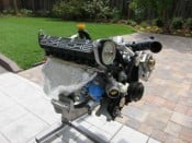
I did an experiment with my spare AFM and shop vac. Right now it's around -1C outside, and around 19C inside. I hoped that the shop vac would displace a constant volume of air, since the motor should turn at a constant speed, regardless of the air temp. Then I could use it to see if the AFM door opens more in colder, denser air, or stays the same.
With a 20C difference in the air temp on either side of this door, it should be a pretty clear test. Some quick research suggests that there should be roughly a 7% change in air density between those temperatures.
With this setup the shop vac pulls enough air to make the AFM output around 2.5v. But surprisingly, opening the door to the cold air makes the output drop by a fairly consistent ~0.02v. So I have to conclude that the shop vac doesn't move a constant volume of air - it moves less air when it's cold, so I can't learn anything from this setup without a way to measure air mass or volume.
So next, when I get around to it, I will put a MAF and an adjustable valve in line with this setup. Then I can note the exact mass air flow and the AFM output, then switch to the cold air and adjust the valve until I'm seeing exactly the same mass air flow, and compare the new AFM output.
That is, unless I find something in the code first that explains the discrepancy!
[1] https://www.w124performance.com/docs/Bo ... s_Aird.pdf
He pretty much nailed exactly my line of reasoning for why it should measure mass. But I don't really understand his argument for why it doesn't.Now, the force that pushes on the measur-
ing vane is a result of the momentum of the
passing air, and momentum is simply the
product (multiple) of mass and velocity. At
first thought, then, it might seem that this
sensor apparatus directly measures mass
flow - the weight of air passing per minute,
which is what matters. In fact, the only way
that the vane could measure the total
momentum of the passing air would be to
bring it all to a complete halt - no air would
flow! Obviously, the vane must obstruct the
airflow as little as possible (the pressure
drop caused by the vane is just 0.017 psi), so
it only measures a small fraction of the total
momentum, and we have no direct way of
knowing what that fraction is. As a result,
the meter is actually measuring volume
flow.
But it's clear that the air temp compensation map I posted doesn't come close to compensating for the density change of air across normal operating temp ranges. So there has to be more to the story.
I did an experiment with my spare AFM and shop vac. Right now it's around -1C outside, and around 19C inside. I hoped that the shop vac would displace a constant volume of air, since the motor should turn at a constant speed, regardless of the air temp. Then I could use it to see if the AFM door opens more in colder, denser air, or stays the same.
With a 20C difference in the air temp on either side of this door, it should be a pretty clear test. Some quick research suggests that there should be roughly a 7% change in air density between those temperatures.
- 20251129_153255.jpg (175.19 KiB) Viewed 844 times
So next, when I get around to it, I will put a MAF and an adjustable valve in line with this setup. Then I can note the exact mass air flow and the AFM output, then switch to the cold air and adjust the valve until I'm seeing exactly the same mass air flow, and compare the new AFM output.
That is, unless I find something in the code first that explains the discrepancy!
[1] https://www.w124performance.com/docs/Bo ... s_Aird.pdf
-
Tom

- Site Admin
- Posts: 8951
- Joined: Fri Jun 25, 2021 2:04 pm
- Location: Silicon Valley, CA
- Has thanked: 936 times
- Been thanked: 4016 times
- Contact:
Love this! I think the MAF will be telling, but in the meantime, maybe consider whether you need to somehow isolate the/any effect of the temperature on both the shop vac efficiency (i.e., cold air cools the windings and reduces resistance, increasing its speed?) and on the potentiometer inside the AFM (i.e., potentiometers lose accuracy as they get colder). An AMP clamp might give you clues on the shop vac, and testing the output of the MAF with a fixed barn door position might give you clues on the AFM pot... The impacts are surely small, but you're dancing on the head of a pin to start... Just spit-balling based on your curious results -- could be a total red herring...johnb wrote: Sat Nov 29, 2025 1:02 pm I have been looking into the question of whether the AFM measures air volume or mass. It's not totally clear. Here's an interesting book[1] that says
He pretty much nailed exactly my line of reasoning for why it should measure mass. But I don't really understand his argument for why it doesn't.Now, the force that pushes on the measur-
ing vane is a result of the momentum of the
passing air, and momentum is simply the
product (multiple) of mass and velocity. At
first thought, then, it might seem that this
sensor apparatus directly measures mass
flow - the weight of air passing per minute,
which is what matters. In fact, the only way
that the vane could measure the total
momentum of the passing air would be to
bring it all to a complete halt - no air would
flow! Obviously, the vane must obstruct the
airflow as little as possible (the pressure
drop caused by the vane is just 0.017 psi), so
it only measures a small fraction of the total
momentum, and we have no direct way of
knowing what that fraction is. As a result,
the meter is actually measuring volume
flow.
But it's clear that the air temp compensation map I posted doesn't come close to compensating for the density change of air across normal operating temp ranges. So there has to be more to the story.
I did an experiment with my spare AFM and shop vac. Right now it's around -1C outside, and around 19C inside. I hoped that the shop vac would displace a constant volume of air, since the motor should turn at a constant speed, regardless of the air temp. Then I could use it to see if the AFM door opens more in colder, denser air, or stays the same.
With a 20C difference in the air temp on either side of this door, it should be a pretty clear test. Some quick research suggests that there should be roughly a 7% change in air density between those temperatures.
20251129_153255.jpg
With this setup the shop vac pulls enough air to make the AFM output around 2.5v. But surprisingly, opening the door to the cold air makes the output drop by a fairly consistent ~0.02v. So I have to conclude that the shop vac doesn't move a constant volume of air - it moves less air when it's cold, so I can't learn anything from this setup without a way to measure air mass or volume.
So next, when I get around to it, I will put a MAF and an adjustable valve in line with this setup. Then I can note the exact mass air flow and the AFM output, then switch to the cold air and adjust the valve until I'm seeing exactly the same mass air flow, and compare the new AFM output.
That is, unless I find something in the code first that explains the discrepancy!
[1] https://www.w124performance.com/docs/Bo ... s_Aird.pdf